How to Calculate the Duty Cycle of Boost Converter

The inductor waveform is the key on how to calculate the duty cycle of boost converter. You can get direct equation for boost converter duty cycle formula from different sites but here I will discuss how it is derived. Meanwhile, a familiar boost converter schematic is shown in Figure 1. The inductor of the boost
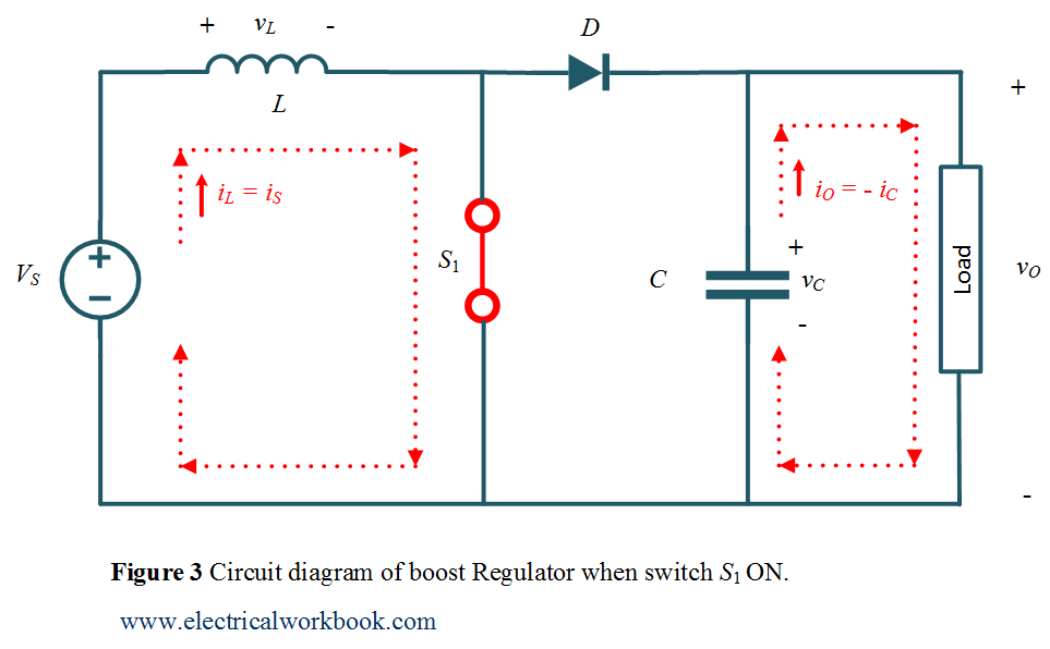
Boost Regulator Average Output Voltage Expression Derivation and Duty Cycle - ElectricalWorkbook

The Buck boost regulator shown in figure has an input voltage of Vs=12V. The duty cycle is 0.25 and the switching frequency is 25 kHz. The inductance L =150 μ H and
Designing Isolated Flyback Converter Circuits: Transformer Design ( Calculating numerical values), Overview of Design Method of PWM AC-DC Flyback Converters

Performance Analysis of a Boost Converter with Components Losses
What is the minimum value of the inductor in a buck-boost converter for it to continue operating in the continuous conduction mode (CCM)? - Quora

Equations and Calculator: Bidirectional Buck and Boost DC-DC Converter

Duty Cycle - an overview
DC to DC buck-boost converter circuit homemade
.png)
Discontinuous Conduction Mode of Simple Converters - Technical Articles
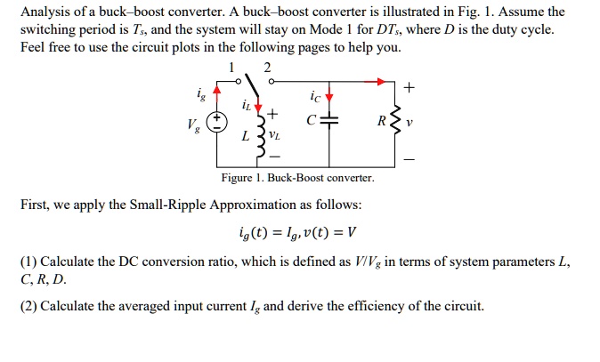
SOLVED: Analysis of a buck-boost converter. A buck-boost converter is illustrated in Fig. 1. Assume the switching period is Ts, and the system will stay on Mode 1 for DTs, where D

DETERMINATION THE EFFECTS OF DUTY CYCLE AND SWITCHING FREQUENCY ON EFFICIENCY OF BOOST CONVERTER FOR FIXED LOAD APPLICATIONS