Schematic diagram of a basic Step-Up converter integrated in a
![](https://www.researchgate.net/publication/278621937/figure/fig2/AS:614197461270534@1523447494432/Schematic-diagram-of-a-basic-Step-Up-converter-integrated-in-a-photovoltaic-generator-PV.png)
Download scientific diagram | Schematic diagram of a basic Step-Up converter integrated in a photovoltaic generator. PV is a photovoltaic panel, PWM is the Pulse Width Modulator. C1, C2, Rp, Rs, L1, D1 and M1 are the discrete elements constituting the electronic circuit (see the text). from publication: Basic MOSFET Based vs Couple-coils Boost Converters for Photovoltaic Generators | Considering the optimization of a photovoltaic system, several studies show the advantage in the choice of a distributed structure. For such structures small power converters such as the boosts and buck converters appear as most appropriate. We have analysed the efficiency of | MOSFET, Photovoltaics and Boost | ResearchGate, the professional network for scientists.
![](https://www.researchgate.net/publication/279871941/figure/fig3/AS:479234104795137@1491269722112/Schematic-diagram-of-Boost-converter.png)
Schematic diagram of Boost converter
![](https://content.instructables.com/FPM/CQPR/HV0KZ00Z/FPMCQPRHV0KZ00Z.bmp?auto=webp&fit=bounds&frame=1)
Step-up Booster : 4 Steps - Instructables
Design Note 183: The LT1370: A 500kHz, 6A Monolithic Boost
![](https://i.pinimg.com/736x/7e/9e/88/7e9e8851ad284777cf0f4481064e9446.jpg)
LM2577 Boost Converter circuit, Step up, Datasheet
![](https://www.homemade-circuits.com/wp-content/uploads/2022/09/5V-to-12V-boost-converter-circuit.jpg)
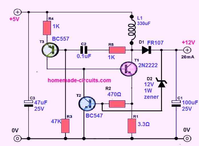
4 Easy Boost Converter Circuits Explained - Homemade Circuit Projects
![](https://www.analog.com/en/_/media/analog/en/landing-pages/technical-articles/micropower-600khz-fixed-frequency-dcdc-converters-stepup-1cell-2cell-battery/figure-1.jpg?la=en&rev=937dc2347f7e4d348c9f78e16e286f43&sc_lang=en)
Micropower 600kHz Fixed-Frequency DC/DC Converters Step Up from a
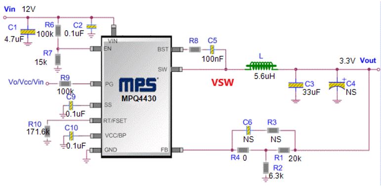
Switch Node Layout Considerations for EMC
40V-30A Adjustable Switching Power Supply
![](https://www.researchgate.net/publication/340029065/figure/fig1/AS:870929106206722@1584657088701/Block-diagram-of-the-proposed-step-up-converter.png)
Block diagram of the proposed step-up converter.
![](https://www.allaboutcircuits.com/uploads/articles/Buck-converter-simulation-schematic.png)
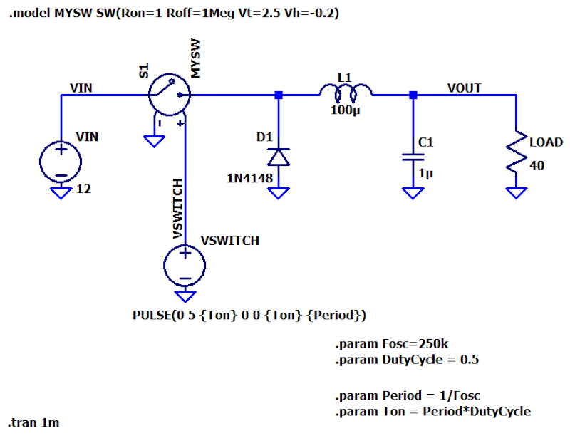
Understanding Switch-Mode Regulation: The Buck Converter
![](https://www.researchgate.net/publication/278621937/figure/fig2/AS:614197461270534@1523447494432/Schematic-diagram-of-a-basic-Step-Up-converter-integrated-in-a-photovoltaic-generator-PV_Q320.jpg)
Schematic diagram of a basic Step-Up converter integrated in a
![](https://www.researchgate.net/profile/Mini-Sujith/publication/281113395/figure/fig2/AS:667600187047944@1536179696613/Circuit-of-High-step-up-dc-dc-converter_Q320.jpg)
Circuit of High-step-up dc-dc converter
![](https://www.researchgate.net/publication/338797685/figure/fig2/AS:11431281179226166@1691166507736/Schematic-diagram-of-the-proposed-high-step-up-converter.png)
Schematic diagram of the proposed high step‐up converter
![](https://www.analog.com/en/_/media/analog/en/landing-pages/design-notes/making-a-voltage-inverter-from-a-buck-stepdown-dcdc-converter/3844fig01.gif?rev=439b393c267f45d58bd7c74d632594b9)
Making a Voltage Inverter from a Buck (Step-Down) DC-DC Converter