Boost Converter Circuit using LM555
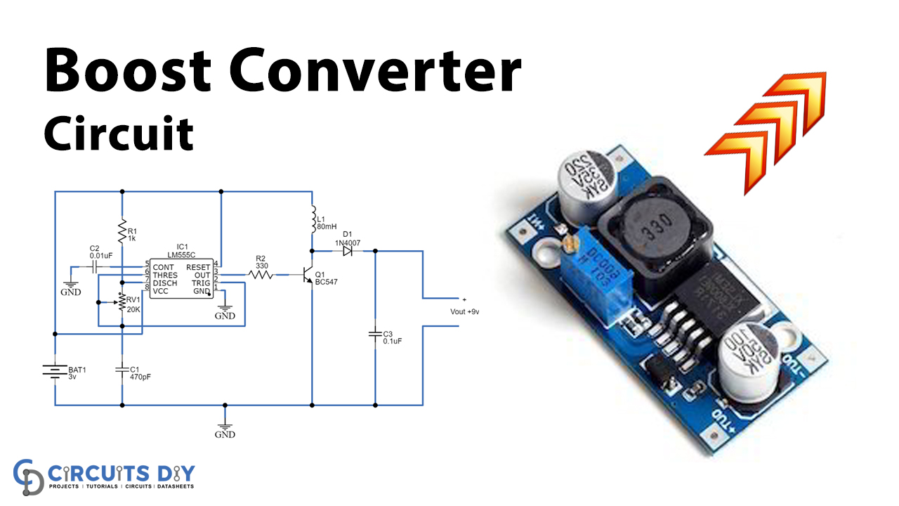
This post explains the circuit of a boost converter made using a 555 time IC, a transistor, and a few passive elements.

Simple DC - DC Boost Converter Using 555 : 4 Steps - Instructables

Buck boost converter - General Electronics - Arduino Forum

Simple DC-DC Boost Converter using 555 Timer IC
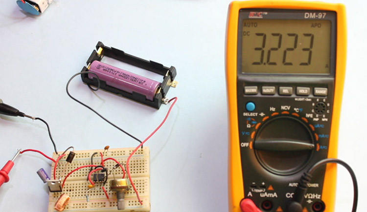
A Simple DC-DC Boost Converter Circuit using 555 Timer IC
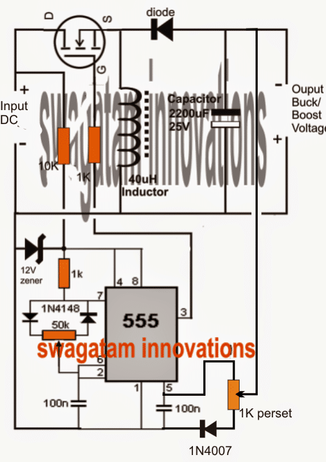
Simple Buck-Boost Converter Circuits Explained - Homemade Circuit Projects
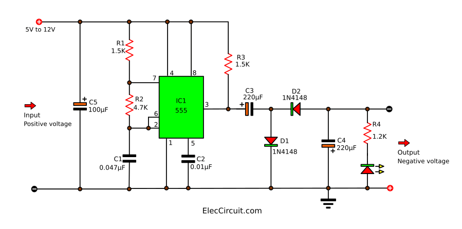
7 ideas of 555 DC boost converter circuits diagram
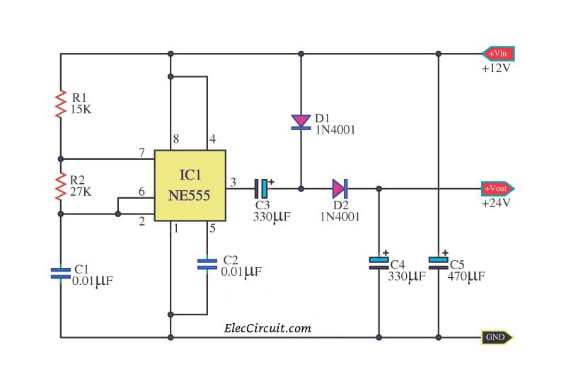
7 ideas of 555 DC boost converter circuits diagram

Add one resistor to give bipolar LM555 oscillator a 50:50 duty cycle - EDN
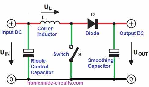
4 Easy Boost Converter Circuits Explained - Homemade Circuit Projects