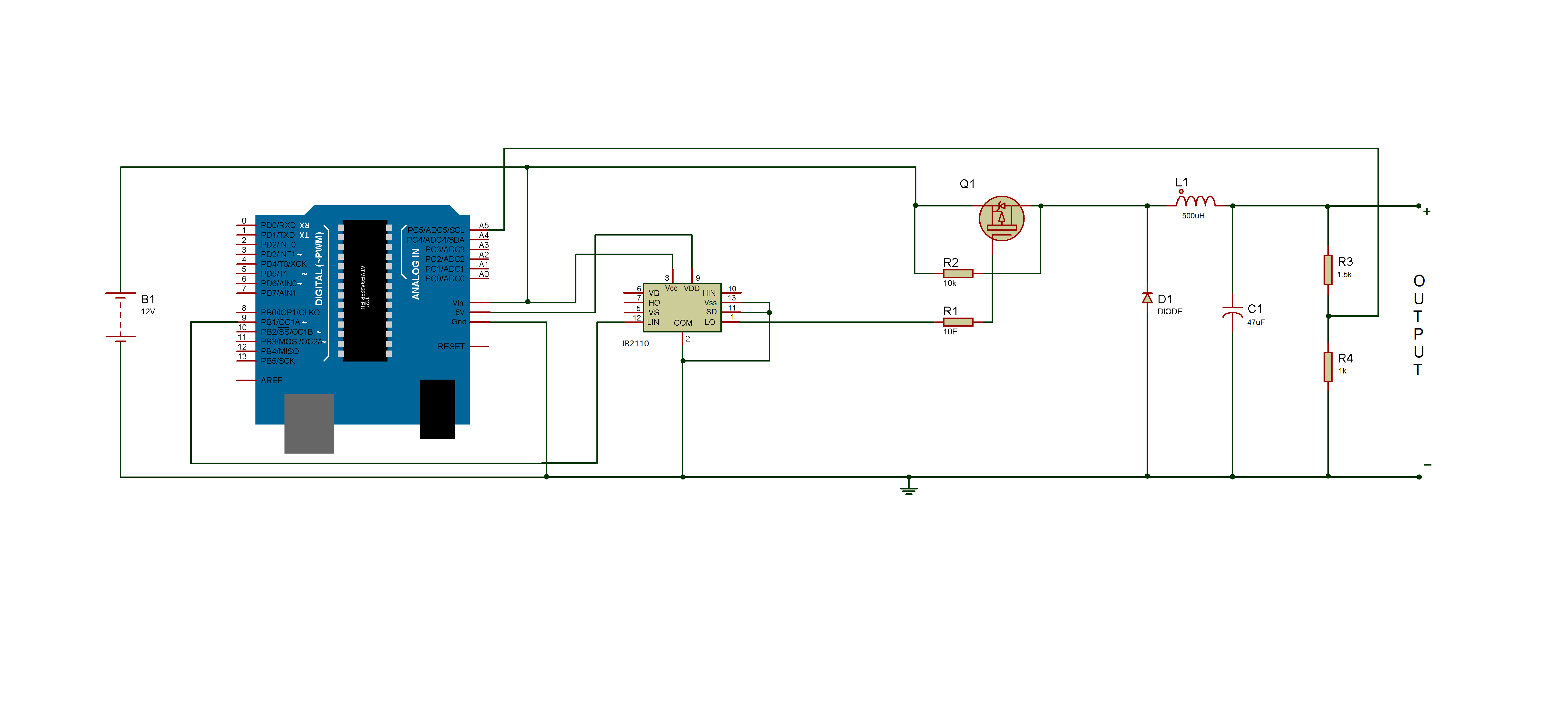
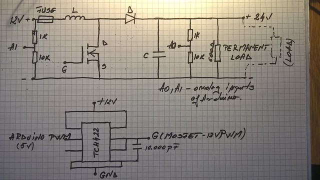
Arduino DC-DC Boost Converter Design Circuit with Control Loop
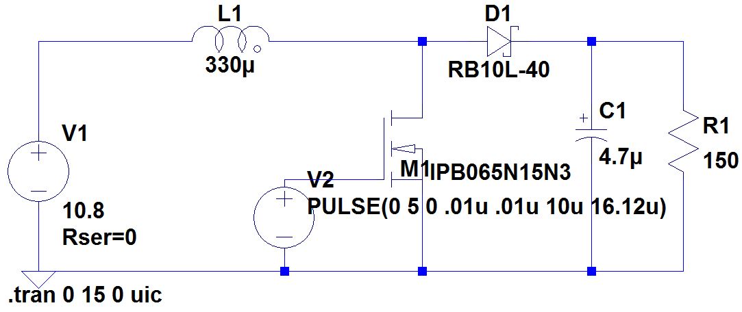
Simple schematic and code for doing DC-DC boost converter control using an Arduino
BOB-09370: This is a breakout board for our non-isolated, 6A DC-to-DC Converter Module. The module can convert any DC voltage between 4.5-14VDC to a selectable voltage between 0.59 and 5.5VDC. To set the output voltage to the desired level, a resistor must be added between the Trim and GND pins. For example, to set the module to output 5V use a 1.34kÎ resistor, or to get 3.3V use a 2.182kÎ. See table 1 in the module's datasheet for more resistor values.
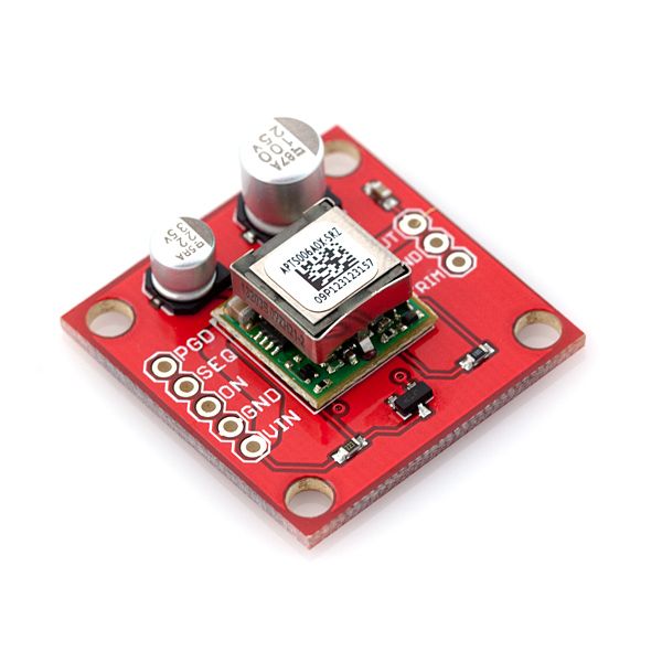
SparkFun DC/DC Converter Breakout
0-30V, 0-7A Adjustable Switching Power Supply [CC-CV with LED]
Arduino DC-DC Boost Converter Design Circuit with Control Loop

The Calculator, DIY DC/DC Boost Calculator

Control Tutorials for MATLAB and Simulink - Feedback Control of a Boost Converter Circuit

The boost converter circuit and its control

Arduino Powered Bi-directional DC-DC Converter : 7 Steps - Instructables

DIY Buck/Boost Converter (Flyback) : 5 Steps (with Pictures) - Instructables
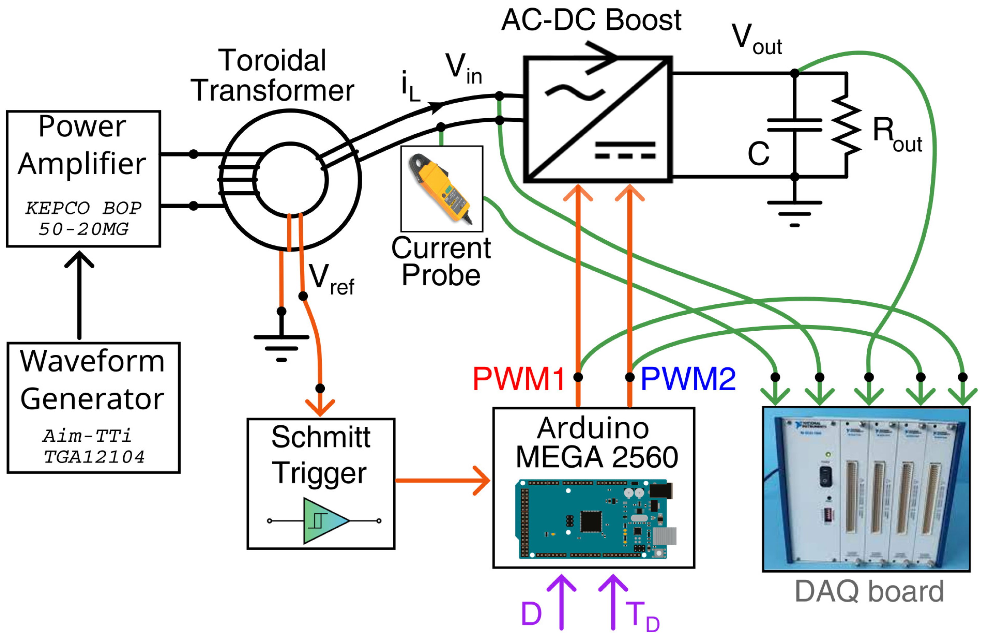
Applied Sciences, Free Full-Text

Introduction to DC-DC Converters

Boost Converter: Basics, Working, Design & Application
Designing Closed Loop Non – Isolated Buck Converter (Part 6/12)
How to make a 12-24V dc-dc boost convertor with arduino